PRODUCT
Y50/250D for butterfly valve test bench
Y50/250D for butterfly valve test bench
This valve testing equipment is mainly used for pressure test of strength and sealing of the DN50-DN350 diameter butterfly valve, also used for pressure test of the similar valves (wafer check valve) and fittings.
The pressure can be adjusted in the specified range (0-12.5Mpa) and the host pressure range(0-250KN). Water pressure can be adjusted in 0-3Mpa.
When the host computer is keeping pressure, the pump is in the state of unloading and saving power, and also with the function of keeping up the pressure and leak alarm.
Ⅱ.Main technical specifications and parameters
|
Serial Number |
Items |
Unit |
Parameter |
|
1 |
Nominal force |
KN |
250 |
|
2 |
Maximum liquid pressure |
Mpa |
12.5 |
|
3 |
mm |
500 |
|
|
4 |
mm |
300 |
|
|
5 |
Size of work table,front and rear* left and right |
mm |
2300*460*1120 |
|
6 |
Height of work table from the ground |
mm |
850 |
|
7 |
L/min |
23 |
|
|
8 |
The flow of hydraulic pump |
L/min |
40 |
|
9 |
Maximum hydraulic pressure |
Mpa |
3 |
|
10 |
Motor power |
KW |
4+3 |
|
11 |
Machine weight |
t |
≈2 |
Ⅲ. Architectural Overview
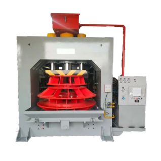
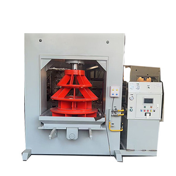
This device is a set of equipment with four-column closed for pressure test, which utilizes the button to control the cylinder with compress and release, control the unloading of median hydraulic system, and keeping up the pressure. Host computer regulator buttons and electrical control box are installed in the host right of the hydraulic station. Hydraulic pumps and hydraulic pressure adjustment (adjustment through electrical contacts) are installed on the positive side of the host, with the overall coordination and easy to be operated.
Ⅳ. Architectural Overview
Hydraulic system consists of gear pump, relief valve, reversing valve, pressure valve, pressure gauge, oil cylinder and piping and other annexes.The motor rotates to drive the gear pump to provide pressure, and reverse the direction through the electromagnetic reversing valve, so that the cylinder piston moves up and down to complete the pressing and releasing operation action. Pressure keeping valve from Paul pressure, may, after pressing the work-piece unloading system, oil cylinder continue pressing the work-piece.The pressure valve plays the role of holding pressure, which can press the work piece in the state of system unloading after pressing the work-piece.
Ⅴ. Hydraulic system description
The hydraulic system is operated by a button on the electric appliance box. When the water pressure is added to the setting (0-3Mpa adjusted by the electric contact pressure gauge), the hydraulic pump automatically stops, but the system is in a state of maintaining the water pressure. When the water pressure need to be removed, move the manual unloading valve. Hydraulic pressure system can be pressed at any time by the pump stop button to stop adding water pressure. Water pressure medium is for water recycling.
Ⅵ. Electrical System Overview
The electrical control of the machine is placed in the electric control box on the right side of the machine. Power supply is used three-phase four wire, AC voltage 380V, frequency 50Hz. Oil pumps and water pumps are driven by three motor. The start and stop of the oil pump motor is realized by the control button of the command element (SB1, SB2). The start and stop of the water pump motor is realized by the control button of the command element (SB3, SB4). Electric contact pressure gauge sends out the signal to control the water pump power failure in the condition of keeping pressure. Power supply, oil pump rotation and water pump rotation has the signal lamp indication, the machine control circuit voltage is 220V.
Ⅶ. Operating vehicle and maintenance
When the equipment installation is completed, join the N32-N46 of hydraulic oil to the oil cylinder and make oil level height is not lower than the lower limit of the level meter. Add water to water tank and storage tank, and make the water level is not lower than the lower limit of the liquid level, connect the three-phase power supply and zero line, then press start key and stop key of the oil pump, press start key and stop key of the water pump, adjust the motor to turn clockwise.Start the oil pump motor, press the "down" button, slowly tighten the pressure regulating valve handle downward, and press the work-piece. Pressure can be adjusted within the range of 0-250KN (0-12.5Mpa) according to the pressure test. Press the pressing button and start the water pump, according to the requirements of pressure test, adjust the pressure through the electric contact pressure gauge within the scope 0-3Mpa, then the water pump stop to hold pressure, please check valve no leakage, move the unloading handle to unload pressure, and loosen the work-piece. Replace or filter hydraulic oil and water medium. Regularly check and add gas, water. Regularly inspect and replace the hydraulic parts and rubber ring.
Ⅷ. Vulnerable parts(see packing list)
Ⅸ. Liquid pressure setting
Liquid pressure can be set according to valve test pressure and diameter calculation. See equipment nominal force and liquid pressure corresponding graph (Figure 5) to determine.