PRODUCT
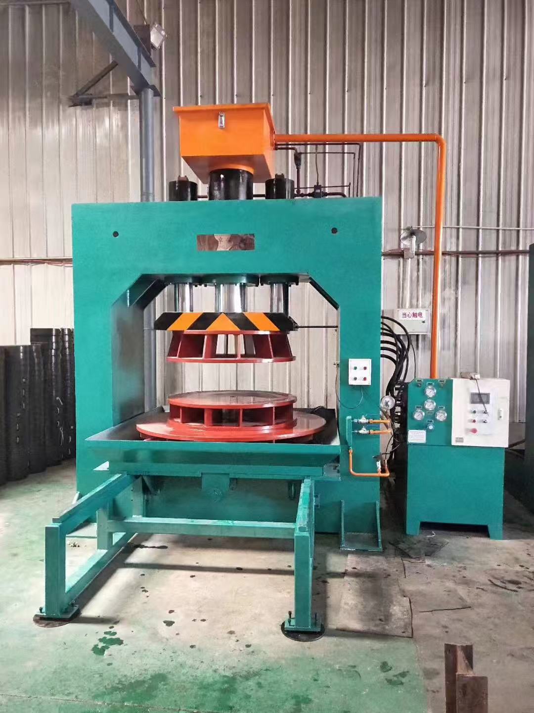
Y300/600 valve test bench machine
Y300/600 valve test bench machine
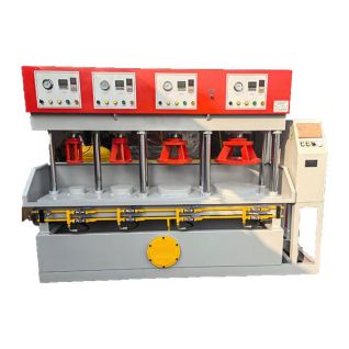
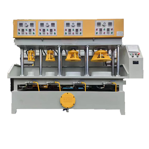
This hydraulic valve testing equipment is mainly used for pressure test of strength and sealing of the DN300mm-600mm diameter butterfly valve, also used for pressure test of the similar valves ( wafer check valve )and fittings.
The pressure can be adjusted in the specified range (0-20Mpa) and the host pressure range(0-630KN). Water pressure should be adjusted in 0-3Mpa.
The hydraulic valve test bench Main technical specifications and parameter
| Serial Number |
Items | Unit | Parameter |
| 1 | Nominal force | KN | 1000 |
| 2 | Maximum liquid pressure | Mpa | 20 |
| 3 | The distance from slider to work table | mm | 600 |
| 4 | Stroke of slider | mm | 550 |
| 5 | Size of slider work table,front and rear* left and right | mm | 900*900 |
| 6 | Height of work table from the ground | mm | 700 |
| 7 | 40ycy plunger pump | L/min | 56 |
| 8 | The flow of hydraulic pump | L/min | 40 |
| 9 | Maximum hydraulic pressure | Mpa | 3 |
| 10 | Motor power | KW | 5.5+3 |
| 11 | Machine weight | t | ≈4 |
Architectural overview
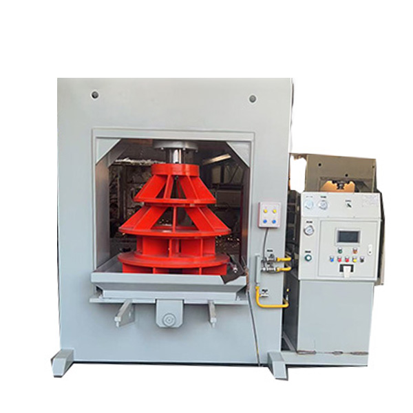
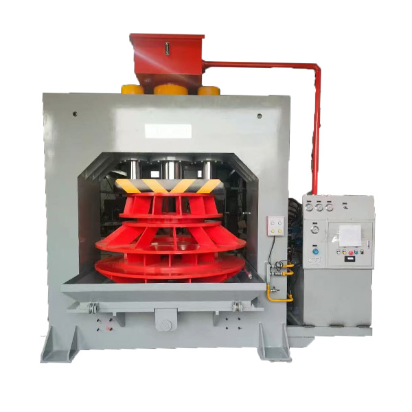
This valve testing equipment is the frame closed type pressure test equipment, which utilizes the solenoid valve to control the cylinder with compress and release, control the unloading of median hydraulic system, and keeping up the pressure. The host computer operates handles, host computer regulator handles and electrical control box are installed in the host right of the hydraulic station. Hydraulic pumps and hydraulic pressure adjust the hydraulic pressure work table slide out and slide in,and hydraulic unloading ball valve are installed in the host right side, with the overall coordination and easy to be operated.
Hydraulic valve testing machine system description
Hydraulic system consists of plunger pump, relief valve, reversing valve, pressure valve, hydraulic One-way value, pressure gauge, oil cylinder and piping and other annexes. The motor rotates to drive the plunger pump to provide pressure, and reverse the direction through the electromagnetic reversing valve, so that the cylinder piston moves up and down to complete the pressing and releasing work-pieces action. The pressure valve plays the role of holding pressure, which can press the work piece in the state of system unloading after pressing the work-pieces.
Water hydraulic system description
The hydraulic system is operated by a button on the electric appliance box. When the water pressure is added to the setting (0-3Mpa adjusted by the electric contact pressure gauge), the hydraulic pump automatically stops, but the system is in a state of maintaining the water pressure. When the water pressure need to be removed, move the manual unloading valve. Hydraulic pressure system can be pressed at any time by the pump stop button to stop adding water pressure. Water pressure medium is for water recycling. The volume of water tank is 400L.
Electrical control description
The electrical control of the machine is placed in the electrical box on the hydraulic station on the right side of the machine. Power supply is used three-phase four wire, AC voltage 380V, frequency 50Hz. Oil pumps and water pumps are driven by motor. The start and stop of the motor is realized by the control buttons of "Start", "Stop", "Hold Delay", "Hold", "Release", "Pull Out" and "Push". The machine control circuit voltage is 220V.
Ⅶ. Operating vehicle and maintenance
Open the air filter of hydraulic station, fill the oil tank with pure N46# hydraulic oil about 200L (which is not lower than the liquid level limit), fill the water tank with medium pressure water about 400L, and then, connect the three-phase power supply and the zero line. Loosen the pressure regulating valve on the front cover plate to test.
Close the air switch, power light. Press the motor start button, the motor rotation. Check the direction of rotation of the motor and the fan blades should turn clockwise. Press the "down" button, slowly tighten the regulator handle to the slider down. Press the "up" button, the slider back, reciprocating action to smooth the slider movement. Then place a parallel pad (height not less than 250 mm) between the slider and the table, and use the joystick to hold the slider against the spacer. Adjust the pressure regulator 0-12.5Mpa for the appropriate pressure.
Regularly clean and maintain the machine. Check the oil level regularly so that it does not fall below the lower limit of the level gauge. Repair and replace the hydraulic components on a regular basis. And once a year of hydraulic oil for a filter or replacement.
Vulnerable parts,see packing list
Liquid pressure setting
Liquid pressure can be set according to valve test pressure and diameter calculation.
Give an example: Valve diameter (m) Valve test pressure P (MPa)
Host nominal force required: N(KN)=(D/2)(D/2)πP*1000
Liquid pressure setting: P1=1.2P2