PRODUCT
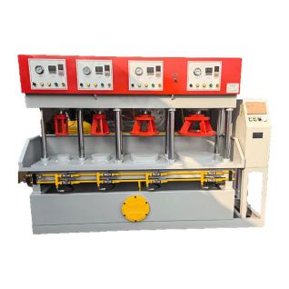
Y 650/1400 valve pressure testing machine
This valve pressure testing machine is designed for pressure testing butterfly valves with a DN650-1400 diameter and similar pipeline valves.
This valve test machine features independent power mechanisms, electrical systems, and pressure testing systems. The hydraulic cylinder is controlled by pushbuttons and operates in a jog-operated manner. The pressure testing system's water pressure is manually controlled by a ball valve. Both the cylinder clamping force and the test water pressure can be freely adjusted within the permitted range. The overall design is coordinated and easy to operate.
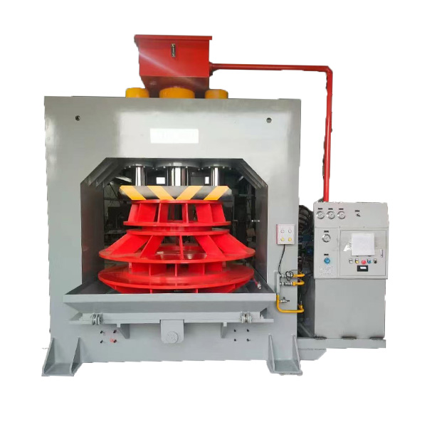
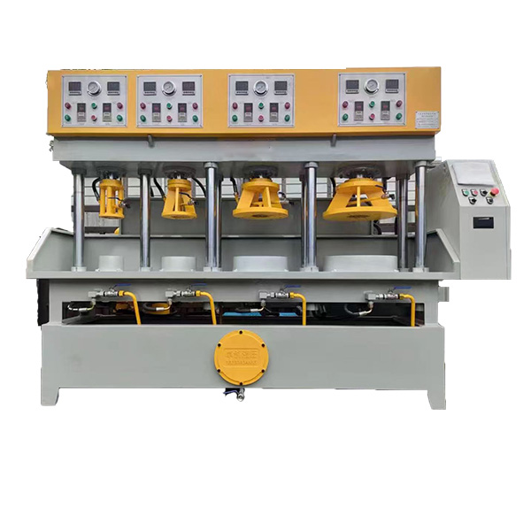
Y 650/1400 valve pressure testing machine
This valve testing equipment is a one-piece structure, primarily consisting of a machine body, cylinder, hydraulic station, pressure-pressing system, and connecting piping. The structure and function of each component are described below.
| NO. | ITEM | UNIT | Specification | |
| 1 | Nominal force | KN | 4000 | |
| 2 | Stroke | mm | 500 | |
| 3 | Net opening |
mm | 720 | |
| 4 | System oil pressure |
MPa | 1-31.5 | |
| 5 | Test water pressure | MPa | 0-3 | |
| 6 | Holding time | s | 0-999 | |
| 7 | Pressure test range |
DN | 650-1400 | |
| 8 | work bench | left and right | mm | 1800 |
| Before and After | mm | 1800 | ||
| 9 | Workbench height from the ground | 650 | 650 | |
| 10 | Outline dimensions |
left and right | mm | 4500 |
Before and After |
mm | 4000 | ||
| height | mm | 3400 | ||
| 11 | Total power |
10.5 | 10.5 | |
| 12 | unit weight | ≈14000 | ≈14000 | |
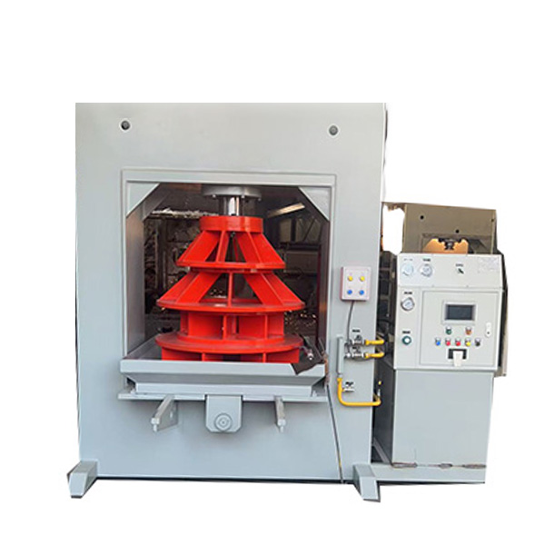
(1)Valve pressure testing Main Machine Body
The machine body is welded together by a machine frame, a cylinder support plate, and a worktable support plate.
(2) Cylinder
The cylinder primarily consists of a cylinder body, connecting flange, piston, piston rod, guide sleeve, and lock nut. The cylinder body and connecting flange are welded together, and the connecting flange is bolted to the crossbeam on the machine body. The guide sleeve is press-fitted onto the cylinder mouth by a lock nut, guiding the piston rod. Both the guide sleeve and piston are sealed with O-rings and Y-type sealing rings. The guide sleeve and piston divide the cylinder into upper and lower chambers, and reciprocating motion is achieved by injecting high-pressure oil into each chamber. The pressure test fixture is connected to the piston via the piston rod and moves synchronously with the piston to achieve process actions such as downward compression and return release. (3) Hydraulic Station
The hydraulic station primarily consists of a fuel tank, fuel pump, motor, reversing valve, and electrical control box. It generates and distributes the hydraulic fluid to achieve various actions, and also controls the operation of the pressure system and the equipment's electrical functions.
The fuel tank is welded from steel plates, with a level gauge mounted on the side and an oil drain port at the bottom. An air filter is mounted on the fuel tank cover, which not only filters the air but also serves as the refill port, filtering the oil during refueling. The fuel pump is integrated with the motor via a connecting bracket and mounted on the fuel tank cover. The reversing valve is mounted on a manifold on the fuel tank cover and electrically controls the diversion and delivery of the hydraulic fluid. The electrical control box, located at the front of the fuel tank cover, controls all electrical functions of the entire equipment.
(4) Pressure System
The pressure system primarily consists of a pressure pump, buffer tank, check valve, pressure test piping, and a pressure gauge. The pressure pump provides high-pressure test medium for the pressure system. The high-pressure medium enters the buffer tank after passing through the check valve. The buffer tank and the pressure plate are connected by a pressure test pipeline. The ball valve controls the addition and removal of water pressure. The pressure gauge is used to display and control the pressure test water pressure and provide a signal for the pressure holding timer function.